注意:因業務調整,暫不接受個人委托測試望見諒。
電路板檢測范圍
硬件,電子產品,制造業,工業設備,電子元件,嵌入式系統,電路設計,半導體,電子工程,電源管理,電子制造,電路分析,電子設備,電路組件,電子通訊,數字電路,模擬電路,集成電路,電路連接
電路板檢測項目
表面貼裝檢測,元件焊接質量檢測,電路板結構檢測,線路通斷測試,阻抗測試,飛針測試,耐壓測試,介電強度測試,結構可靠性測試,熱沖擊測試,濕熱循環測試,鹽霧測試,靜電放電測試,ESD測試,EMC測試,射頻測試,高頻測試,噪聲測試,震動測試,沖擊測試,可靠性壽命測試
電路板檢測方法
Visual Inspection: This method involves examining the circuit board with the naked eye to detect any visible defects such as cracks, scratches, or soldering issues.
X-ray Inspection: X-ray imaging can be used to inspect the internal structure of the circuit board, revealing hidden defects such as faulty solder joints or internal shorts.
Electrical Testing: This method involves sending electrical signals through the circuit board to test for proper functionality and identify any faulty components or connections.
Thermal Imaging: Thermal cameras can be used to detect hotspots on the circuit board, indicating potential issues such as overheating components or poor thermal management.
Scanning Electron Microscopy (SEM): SEM can be used to provide high-resolution images of the circuit board surface, allowing for detailed inspection of the circuit traces and components.
Microsection Analysis: This method involves slicing a small portion of the circuit board for microscopic examination to identify defects such as delamination, voids, or cracks in the layers.
Ion Chromatography: Ion chromatography can be used to analyze the cleanliness of the circuit board by detecting and measuring ionic residues left behind during the manufacturing process.
Environmental Testing: Environmental testing involves subjecting the circuit board to various environmental conditions such as temperature, humidity, and vibration to assess its performance and reliability under different circumstances.
Component Testing: Individual components on the circuit board can be tested using specific methods such as continuity checks, capacitance measurements, or in-circuit testing to verify their functionality.
Failure Analysis: In case of a malfunctioning circuit board, failure analysis techniques can be employed to identify the root cause of the issue, which may involve a combination of different testing methods and analysis tools.
電路板檢測儀器
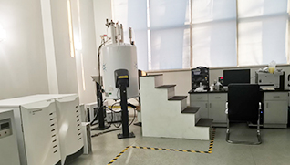
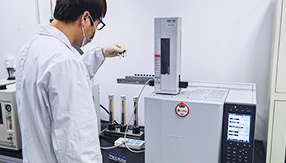
示波器, 頻譜儀, 萬用表, 邏輯分析儀, 示波掃描儀, 模擬信號發生器, 數字信號發生器, 電源源波器, 高阻計, 頻率計, 阻抗分析儀, 熱像儀, 核磁共振儀, 紫外-可見吸收光譜儀, 質譜儀, 氣相色譜儀, 液相色譜儀, 微量分析儀, 表面掃描儀, X射線衍射儀
電路板檢測標準
CNS 10850-2000:印刷電路板通則
CNS 10851-2000:多層印刷電路板
QJ 2830-1996:印制電路板導軌規范
QJ 3103A-2011:印制電路板設計要求
CNS 10852-2000:印刷電路板檢驗法
CNS 10562-2000:單、雙面印刷電路板
QJ 201A-1999:印制電路板通用規范
QJ 519A-1999:印制電路板試驗方法
HG/T 4239-2011(2017):印刷電路板用銀鹽膠片
HG/T 4396-2012:印刷電路板用重氮鹽膠片
HG/T 4396-2012(2017):印刷電路板用重氮鹽膠片
CNS 14735-3-2003:印刷電路板設計與應用
SJ 20904-2004:軟基材微波電路板設計指南
HG/T 4239-2011:印刷電路板用銀鹽膠片
GB 51127-2015:印刷電路板工廠設計規范
QJ 2152-1991:撓性印制電路板技術條件
QJ 518-1980:印制電路板外形尺寸系列
SJ 21150-2016:微波組件印制電路板設計指南
CNS 8427-1982:印刷電路板用玻璃纖維席
QJ 831B-2011:航天用多層印制電路板通用規范
SJ 20776-2000:印制電路板版圖數據格式 Gerber
QJ 3015-1998:印制電路板圖形轉移工藝技術要求
QJ 832B-2011:航天用多層印制電路板試驗方法
HJ 450-2008:清潔生產標準 印制電路板制造業
SJ 21548-2020:印制電路板組裝件靜態應變測試方法
CNS 14735-9-2003:具導孔之軟性多層印刷電路板規格
QJ 2776-1995:印制電路板通斷測試要求和方法
QJ 1890-1990:印制電路板對外連接方式及設計規范
GB/T 33377-2016:軟性電路板覆蓋膜用非硅離型材料
QJ 1462A-1999:印制電路板酸性光亮鍍銅工藝技術要求


實驗儀器




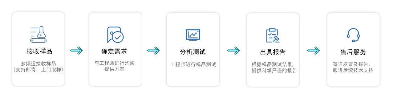
測試流程
注意事項
1.具體的試驗周期以工程師告知的為準。
2.文章中的圖片或者標準以及具體的試驗方案僅供參考,因為每個樣品和項目都有所不同,所以最終以工程師告知的為準。
3.關于(樣品量)的需求,最好是先咨詢我們的工程師確定,避免不必要的樣品損失。
4.加急試驗周期一般是五個工作日左右,部分樣品有所差異
5.如果對于(電路板檢測)還有什么疑問,可以咨詢我們的工程師為您一一解答。
- 苯磺酰氯測試閱讀:21
- 減震逐步檢測閱讀:10
- 吸糞車測試閱讀:16
- 雜類燈座測試閱讀:18
- 浸漬膠膜紙飾面膠合板和細木工板檢測閱讀:39
- 底泥檢測閱讀:8
- 銅及銅合金無縫翅片管檢測閱讀:7
- 報紙測試閱讀:9
- 釉面鋼化及釉面半鋼化玻璃檢測閱讀:12
- 復印紙檢測閱讀:5

-
服務保障 一對一品質服務
-
定制方案 提供非標定制試驗方案
-
保密協議 簽訂保密協議,嚴格保護客戶隱私
-
全國取樣/寄樣 全國上門取樣/寄樣/現場試驗

